Controlling Electrostatic Discharge ESD in Cleanrooms

Kjeld Lund May 30, 2025
Semiconductor Cleanroom Manufacturing

Introduction


Electrostatic discharge (ESD) is a phenomenon that occurs when there is a sudden flow of electricity between two electrically charged objects. This discharge can be incredibly damaging, especially in environments that handle sensitive electronic components or biological materials. Cleanrooms, which are meticulously controlled environments used for various applications like semiconductor manufacturing, pharmaceuticals, biotechnology, and medical device production, must be designed to control all potential sources of contamination. ESD is one of the most critical factors in maintaining the integrity of cleanroom processes and the safety of the equipment and materials being handled.


In this article, we will delve into the concept of electrostatic discharge, its impact on cleanroom environments, the best practices for controlling ESD, and the technologies used to prevent its occurrence in sensitive areas. Understanding the complexities of ESD and its control is essential for ensuring the quality, safety, and efficiency of cleanroom operations, particularly in industries dealing with advanced electronics, sensitive biological research, or high-precision manufacturing.


What is Electrostatic Discharge (ESD)?


Electrostatic discharge refers to the sudden transfer of electrostatic charge between two objects of different electrical potentials. This can happen when one object, often a human body, carries an electrostatic charge and comes into contact with another object, like a piece of sensitive electronic equipment or a semiconductor wafer. The charge transfer that occurs during ESD can result in short circuits, malfunctioning devices, or permanent damage to components that cannot be repaired.


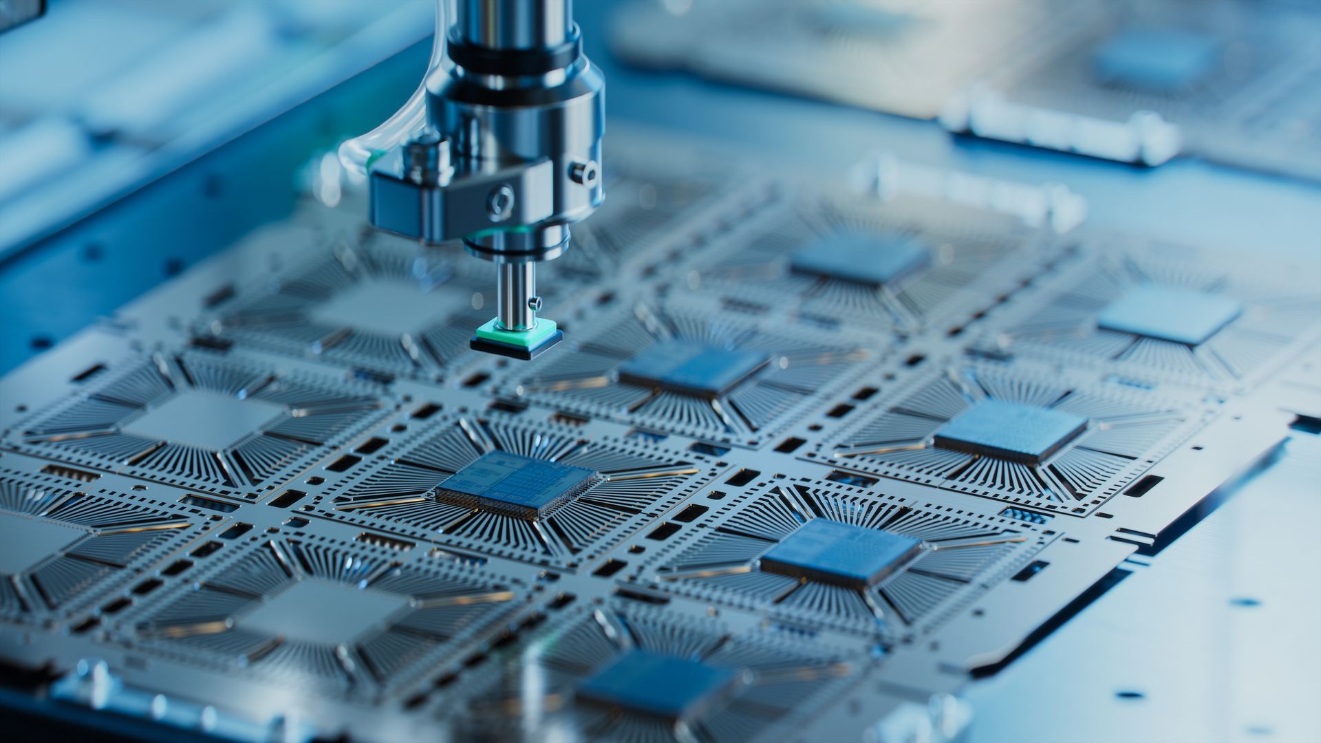
In cleanrooms, where precision is critical, and equipment must perform at optimal levels, even the smallest ESD event can have disastrous consequences. For example, in semiconductor manufacturing, a single static discharge could render an entire wafer batch unusable, leading to financial losses and delays in production schedules. In the pharmaceutical or medical device industry, the presence of static electricity could cause contamination or negatively affect the quality of drugs, devices, or biological samples.


The Impact of ESD on Cleanrooms


The impact of ESD in cleanrooms can be far-reaching, affecting both the safety of workers and the quality of the products or research being conducted.


Some of the main risks of ESD in cleanroom environments include:


  1. Damage to Electronic Components: In cleanrooms, especially in industries like semiconductor manufacturing, electronics, and aerospace, ESD is one of the leading causes of damage to sensitive components. Modern electronic devices are increasingly smaller and more complex, with increasingly delicate circuits. Static electricity can destroy or degrade the functionality of integrated circuits, transistors, microchips, and other critical components, leading to failed products and costly losses.
  2. Contamination Risk: In certain cleanroom environments, such as those used in the pharmaceutical or biotechnology sectors, ESD can create sparks that ignite combustible or flammable substances. This poses a serious safety risk, especially in areas where hazardous chemicals or volatile compounds are used or stored. Additionally, uncontrolled ESD can lead to the movement of particles, which can interfere with sterile processes or experiments, further compromising the cleanliness of the environment.
  3. Loss of Product Yield: In semiconductor manufacturing, even a single ESD event can result in the loss of entire product batches. Given the high value of materials and components, the financial implications of an ESD-induced failure can be significant. For example, a microchip that is subjected to an ESD event might be rendered useless, forcing manufacturers to discard it and start the production process over.
  4. Inconsistent Test Results: In laboratories that rely on controlled environments, such as research labs in biotechnology or pharmaceuticals, ESD can introduce unpredictable variables into experiments. For example, in cell culture research, sensitive biological samples can be affected by minor static charges that disrupt the growth of cells or alter experimental results. This can lead to unreliable data, delays in research, and, in some cases, the need to repeat entire experimental procedures.


Best Practices for Controlling ESD in Cleanrooms


Controlling electrostatic discharge in cleanrooms is a comprehensive effort that requires the integration of various technologies, design elements, and operational practices. Cleanroom environments should be designed to minimize the accumulation and discharge of static electricity, and personnel should be trained to follow proper procedures to prevent static buildup. Here are several best practices to control ESD effectively:


1. Control of Ambient Humidity


One of the most effective ways to reduce the buildup of static electricity in cleanrooms is through the careful management of humidity levels. Electrostatic charges are more likely to accumulate in environments with low humidity, as the lack of moisture in the air allows the static charge to build up and discharge more readily. By increasing humidity levels to a range of 40-60%, static buildup can be minimized.


Many cleanrooms, particularly in industries like electronics and pharmaceuticals, use humidifiers as part of their HVAC systems to maintain the desired humidity levels. Proper control of temperature and humidity not only reduces static electricity but also improves overall air quality, which is important for maintaining a clean environment.


2. Anti-Static Flooring


Flooring is a critical element in controlling ESD in cleanrooms. The materials used in cleanroom floors must be selected based on their ability to dissipate static charges and prevent static buildup. Anti-static and conductive flooring options, such as vinyl and rubber with conductive additives, are commonly used to control ESD in cleanrooms.


  • Conductive Floors: Conductive flooring allows static electricity to travel safely to the ground, preventing static charges from accumulating on surfaces or equipment.
  • Static-Dissipative Floors: These floors offer a slightly slower dissipation of charge, providing a safe environment for sensitive electronic components while minimizing the risk of electrical discharge.


It is essential to ground the flooring system correctly to ensure that any accumulated static charges are safely directed away from critical equipment and personnel.


3. ESD-Safe Workstations and Furniture


Workstations and furniture in cleanrooms must also be designed to minimize static buildup. Anti-static or ESD-safe work surfaces and chairs are commonly used to prevent electrostatic charge accumulation during work. These workstations are often equipped with grounding straps, which provide a pathway for any built-up static electricity to be safely discharged to the ground.


Other ESD-safe equipment, such as ionizers, are also used to neutralize static charges in the work area. Ionizers generate ions that balance out the charge differential between objects, ensuring that static buildup does not reach dangerous levels.


4. Personal Protective Equipment (PPE)


Personnel working in cleanrooms must wear appropriate personal protective equipment to prevent the introduction of static charges into the environment. This includes:


  • ESD Wrist Straps: These wrist straps are designed to discharge any static electricity that may accumulate on a person’s body. They should be worn at all times when working with sensitive electronic components or equipment.
  • ESD Gloves: Non-static generating gloves are essential to prevent the transfer of static electricity from human hands to products or work surfaces.
  • Conductive Footwear: Anti-static or conductive footwear is crucial in maintaining a constant grounding path for personnel, preventing the buildup of static charges as they move around the cleanroom.


Proper training and awareness of static control practices are critical for personnel to minimize the risks associated with ESD. Workers should be educated on the importance of ESD control, how to handle sensitive equipment, and how to use anti-static clothing and accessories effectively.


5. Ionization Systems


Ionization systems are often installed in cleanrooms to neutralize static charges in the air. These systems generate ions, which help neutralize charged surfaces by balancing the electrical charge, thereby preventing static buildup.


Ionizers are particularly useful in areas where humidity levels cannot be easily controlled or in processes that require extremely low levels of contamination.


Ionization is especially critical in environments where sensitive electronic components are handled, such as semiconductor fabrication or assembly lines for consumer electronics. In these environments, the presence of any static charge can lead to costly damage to microchips, circuit boards, or other components.


6. ESD-Safe Packaging


For cleanrooms involved in electronics assembly or semiconductor manufacturing, packaging materials must also be ESD-safe to protect sensitive components during transport and storage.


Conductive or static-dissipative materials, such as antistatic bags, trays, and boxes, are used to ensure that components are not exposed to static charges.


Monitoring and Maintenance


To ensure that ESD control measures remain effective, cleanroom environments must be regularly monitored and maintained. This includes:


  • Routine Grounding Inspections: Periodic checks of the grounding system (including floors, workstations, and personnel equipment) are essential to ensure that all components are properly grounded.
  • Air Quality and Humidity Monitoring: Environmental monitoring systems should be installed to track humidity levels, temperature, and static charge buildup in real-time. This ensures that conditions remain optimal for controlling ESD and minimizing risks to sensitive equipment.
  • Training and Protocols: Cleanroom personnel should undergo regular training on ESD control protocols, including handling ESD-sensitive equipment, using proper PPE, and understanding the risks associated with electrostatic discharge.


Conclusion


Controlling electrostatic discharge in cleanrooms is a critical component of maintaining the integrity of sensitive materials, equipment, and processes. ESD can cause irreparable damage to electronic components, lead to contamination in sterile environments, and even cause safety hazards.


Through proper design, careful material selection, and the implementation of best practices, cleanrooms can effectively control ESD and minimize its impact on operations.


By controlling ambient humidity, installing anti-static flooring, utilizing ESD-safe workstations, equipping personnel with proper protective gear, and using ionization systems, cleanroom operators can create an environment that minimizes the risks associated with electrostatic discharge.


With continued monitoring and maintenance, cleanrooms can ensure that the integrity of research, manufacturing, and production processes remains intact, supporting industries where precision and safety are paramount.


Read more: All About Cleanrooms - The ultimate Guide


Automated pharmaceutical production line filling vials with clear liquid.
By Kjeld Lund 27 February 2026 February 27, 2026
Cleanroom Commissioning: Integrating Building Services and Process Requirements 1. Introduction Cleanroom commissioning is a structured, engineering-driven process that ensures building services, HVAC systems, automation controls, and process-specific requirements are harmonized before qualification and routine operation. While ISO 14644 defines the performance criteria and GMP Annex 1 establishes regulatory expectations, commissioning verifies that the facility’s mechanical, electrical, and control systems have been functionally tested, documented, and optimized to support cleanroom performance. Effective commissioning reduces qualification risk, compresses project timelines, and provides a reliable foundation for DQ–IQ–OQ–PQ activities. This article outlines a technically rigorous approach to commissioning cleanrooms by integrating building services with process and operational needs. 2. Commissioning Objectives and Scope Cleanroom commissioning goes beyond standard HVAC commissioning by incorporating contamination-control, process compatibility, and regulatory compliance considerations. Primary objectives include: Confirming that building services deliver the environmental conditions required by the URS. Verifying that HVAC, electrical, monitoring, and automation systems perform according to design intent. Ensuring seamless integration of process equipment, personnel flow, and material flow. Establishing documented evidence that supports subsequent IQ/OQ/PQ activities. Commissioning scope typically covers mechanical (HVAC), electrical, process utilities, automation, controls, fire protection, and architectural systems relevant to environmental stability. 3. Relationship Between Commissioning and Qualification Commissioning and qualification are distinct but interdependent processes. Commissioning verifies functional performance and ensures systems operate safely, reliably, and in accordance with the design. Qualification demonstrates that the facility meets regulatory, contamination-control, and process requirements defined in the URS and CCS. A well-executed commissioning effort reduces qualification deviations, accelerates OQ, and provides high-quality baselines for PQ. 4. Commissioning Workflow Structure A structured commissioning plan provides transparency, traceability, and alignment with design requirements. Typical stages include: Pre-Commissioning: Documentation review, installation checks, and power-up inspections. Static Commissioning: Verification of mechanical and electrical installation quality. Dynamic Commissioning: Functional testing under powered and operational conditions. Integrated Systems Testing (IST): Validation of system-to-system interactions, including alarms, interlocks, and fail-safes. Handover to Qualification: Compilation of commissioning results and resolution of deficiencies. Each stage must be traceable to the design documents, URS, and Basis of Design (BOD). 5. HVAC Commissioning Essentials HVAC systems are the backbone of cleanroom environmental control. Commissioning must demonstrate that airflow, pressure, temperature, and humidity targets are reliably achievable. Critical HVAC commissioning activities: Airflow verification: Measuring supply, return, and exhaust volumes to confirm balance and cascade stability. Pressure cascade establishment: Testing differential pressures between zones under at-rest and disturbed conditions. Filter installation integrity: Ensuring HEPA/ULPA filters and housings are correctly seated before OQ integrity testing. Damper and control valve tuning: Aligning actuator positions and control algorithms with design assumptions. Thermal stability verification: Confirming temperature and humidity responsiveness under varying loads. Mechanical commissioning data form the baseline for OQ environmental verification. 6. Integration of Building Automation and Monitoring Systems Cleanrooms rely on automation for stable control of critical environmental parameters. Key commissioning considerations: BMS/EMS functional testing: Verifying setpoint control, signal scaling, trending, and alarm logic. Interlocks and dependencies: Testing door interlocks, pressure-loss alarms, fan failures, and safe-shutdown sequences. Sensor calibration: Ensuring pressure, temperature, humidity, and airflow sensors are calibrated and traceable. Redundancy and failover: Validating that redundant fans, UPS systems, or emergency power supplies respond appropriately. Automation commissioning provides the functional evidence required to support qualification, monitoring strategy development, and ongoing lifecycle control. 7. Integration of Utility and Process Services Process utilities must operate in harmony with the cleanroom environment, especially in GMP-regulated facilities. Core utility commissioning activities include: Clean utilities: Verifying functionality of compressed air, chilled water, process gases, and vacuum systems. Gowning and hygiene facilities: Ensuring airlocks, sinks, and hand dryers support contamination-control workflows. Waste and exhaust systems: Confirming containment and flow direction for hazardous or high-particulate loads. Lighting and emergency systems: Ensuring visual quality and safety without introducing contamination or turbulence. Utility commissioning ensures the cleanroom can support full process operations without compromising environmental conditions. 8. Architectural and Envelope Commissioning The cleanroom envelope establishes the physical barriers needed to control contamination and maintain pressurization. Key architectural commissioning checks: Verification of panel integrity, sealing, and non-shedding finishes. Door alignment, closure force, and leakage performance. Integrity of glazing, pass-throughs, and service panels. Surface continuity, cleanability, and compliance with hygienic design principles. Access to mechanical spaces without exposing clean areas to uncontrolled contamination. Architectural performance strongly influences the ability to maintain pressure cascades and achieve classification targets. 9. Integrated Systems Testing (IST) IST validates the full interaction of cleanroom subsystems under realistic scenarios. This is particularly important for GMP facilities where system interdependencies affect contamination control. Typical IST tests include: Power failure and restoration: Verifying controlled shutdown and recovery of HVAC, monitoring, and interlocks. Fire alarm activation: Confirming damper positioning, pressurization shifts, and emergency responses. Door operation simulations: Evaluating transient pressure responses and interlock performance. Equipment heat-load simulation: Testing environmental stability under modeled process conditions. HVAC-facility coordination: Ensuring airflow patterns remain stable when multiple units ramp up or modulate. IST results are essential inputs for OQ/PQ risk assessment. 10. Documentation and Traceability Commissioning documentation must be complete, organized, and traceable to support qualification and regulatory audits. Required documentation typically includes: Commissioning plans, protocols, and test scripts. Installation and functional verification records. Calibration certificates and equipment lists. As-built drawings, control sequences, and airflow balance reports. Deficiency logs and corrective actions. Final commissioning summary report. A thorough documentation package reduces ambiguity during qualification and provides clear evidence of engineering due diligence. 11. Transition to Qualification (IQ–OQ–PQ) After commissioning, qualification teams rely on the commissioning data as verified baselines. Linkages include: IQ: Uses installation records, calibration data, and as-built documentation. OQ: Builds on airflow, pressure, and control-system performance data to verify environmental conditions. PQ: Relies on operational insights from IST and utility tests to validate process performance. A seamless transition between commissioning and qualification minimizes rework and enhances regulatory compliance. 12. Conclusion Cleanroom commissioning is a critical step in ensuring that building services and process requirements form a cohesive, fully functional system before regulatory qualification. By rigorously testing HVAC, automation, utilities, and architectural components—and by validating their interactions through IST—commissioning provides the technical foundation for reliable cleanroom performance. When executed with precision and clear documentation, commissioning strengthens contamination control, reduces risk, and enhances the long-term operational stability of regulated facilities. Read more here: About Cleanrooms: The ultimate Guide
Brown powder exploding against a white background.
By Kjeld Lund February 20, 2026 February 20, 2026
Precision Control of Pressure Cascades in Multi-Zone Facilities 1. Introduction Pressure cascades are a foundational element of contamination control in multi-zone cleanroom facilities. Whether the target is protecting sterile products, preventing cross-contamination, or ensuring environmental containment, the ability to maintain well-defined differential pressures between adjacent rooms is essential for compliance with ISO 14644 , GMP Annex 1 , and sector-specific regulatory frameworks. Precision pressure control enables directional airflow from cleaner to less clean (or, in containment applications, the reverse), ensuring that contaminants cannot migrate across boundaries. This article presents a technically robust, engineering-focused overview of strategies for designing, implementing, and maintaining stable pressure cascades in complex cleanroom environments. 2. Fundamentals of Pressure Cascade Design A pressure cascade establishes a controlled airflow direction between rooms. Cleanrooms typically maintain positive pressure relative to surrounding areas, whereas containment suites (e.g., cytotoxic or BSL environments) may maintain negative pressure to prevent hazardous material release. Key engineering objectives: Maintain defined pressure differentials, commonly 10–15 Pa between critical cleanroom grades and ≥5 Pa between support zones. Ensure airflow directionality remains stable under expected operational conditions, including personnel movement and door cycling. Integrate pressure control with the overall heating, ventilation, and air conditioning (HVAC) strategy and with the facility’s Contamination Control Strategy (CCS). Pressure cascades must be defined during Design Qualification (DQ) and supported by detailed airflow and balance calculations. 3. Determining Target Pressure Differentials Target values depend on regulatory classification, process risk, and architectural constraints. Common industry values: ISO 5 → ISO 7 transitions: 10–15 Pa positive differential. ISO 7 → ISO 8 transitions: 5–10 Pa. Cleanroom envelope → unclassified areas: 10–30 Pa, depending on infiltration risk. Containment zones (negative pressure): –25 to –50 Pa relative to adjacent safe areas, depending on hazard classification. Selection of pressure levels must consider: Leakage paths (e.g., door margins, pass-throughs, panel joints). HVAC supply/exhaust balance requirements. Structural constraints that affect room airtightness. Safety factors for peak infiltration during operations. 4. Supply, Return, and Exhaust Balance Strategies Achieving stable pressure requires precise control of volumetric airflow. Primary balancing strategies: Supply-dominant control (positive pressure zones): Supply airflow exceeds return/exhaust. Exhaust-dominant control (negative pressure zones): Exhaust exceeds supply to maintain containment. Neutral-buffered rooms: Used between zones where either excessive positive or negative pressure would be undesirable. Engineering calculations must account for: Door leakage rates at closed and partially opened conditions. Equipment penetrations and pass-throughs. Variability in FFU and terminal HEPA performance curves. Seasonal density changes in supply air that affect mass flow. Airflow balance typically forms the basis for both initial HVAC design and control-system tuning during OQ. 5. Control System Architecture for Pressure Regulation Modern pressure cascades rely on a combination of hardware and control strategies to ensure stability under dynamic conditions. Essential system components: Differential pressure sensors: High-accuracy transmitters with calibration traceability, placed between each zone pair. Variable Air Volume (VAV) boxes: Modulate supply or return airflow to maintain the setpoint. Exhaust control valves/dampers: Particularly critical in negative-pressure zones. Airflow monitoring stations: Provide mass-flow verification for high-precision control loops. Building Management System (BMS) or EMS integration: Enables setpoint enforcement, alarms, trending, and interlocks. Control strategies: Cascade control loops: Primary (pressure) loop driving secondary (airflow) loops for improved response. Direct supply modulation: Adjusts supply airflow to maintain pressure. Return modulation: Often used where supply airflow must remain stable for temperature or humidity control. Hybrid strategies: Combining supply and return modulation for high-stability applications such as Grade B aseptic areas. 6. Managing Dynamic Conditions and Transients Door openings, personnel movement, and equipment operation introduce transient disturbances that can destabilize pressure cascades. Engineering techniques to manage transients: Airlock design: Provides staged pressure transitions and minimizes direct room-to-room pressure impacts. Interlocked doors: Prevent simultaneous opening of two doors within airlocks. High-response actuators and VAVs: Reduce pressure drift during sudden disturbances. Buffer airflow: Slight over- or under-supply margin to absorb transient conditions. Door automation: Slow-open/slow-close mechanisms reduce airflow shock loads. Transient simulations—either through CFD or simplified airflow modelling—are valuable during DQ for assessing worst-case scenarios. 7. Architectural Airtightness and Leakage Control Room leakage strongly influences achievable pressure stability and energy efficiency. Best practices: Seal all penetrations, utility lines, electrical conduits, and panel joints with low-VOC, non-shedding sealants. Use gasketed, tight-tolerance cleanroom doors with verified leakage rates. Minimize uncontrolled leakage paths within wall systems, ceiling voids, and raised floors. Validate airtightness through room pressure decay tests where appropriate. Improving airtightness often reduces the airflow required to maintain pressure differentials, lowering lifecycle operating costs. 8. Sensor Placement and Calibration Strategies Accurate pressure control depends heavily on proper placement and maintenance of differential pressure sensors. Placement guidelines: Sensors should measure pressure between rooms directly, not relative to corridor air that may fluctuate. Install measurement ports away from supply diffusers and high-velocity zones to avoid local bias. Maintain consistent elevation when comparing multiple sensors for cascade alignment. Calibration considerations: Perform initial calibration during IQ with traceable standards. Recalibrate at intervals defined by risk assessment—typically 6–12 months. Verify readings during every OQ using calibrated reference instruments. 9. Integration With Environmental Monitoring and Alarms Pressure differentials are classified as critical or major environmental parameters depending on the process. Monitoring systems must provide continuous assurance. Key features for compliant systems: Real-time trending with audit trails. Alarm setpoints with justified action/alert limits (e.g., 10 Pa target with 6 Pa alert and 4 Pa action). Door status logging to correlate excursions with operational events. Interlocks that deactivate operations or signal operators when pressure falls below safe limits. Proper alarm integration is a requirement under GMP Annex 1 to ensure ongoing contamination control. 10. Verification and Qualification of Pressure Cascades Pressure cascade performance must be demonstrated through structured qualification activities. During OQ: Measure differential pressure stability under at-rest conditions. Verify response time to disturbances such as door openings. Confirm that airflow balancing matches design assumptions used in DQ. During PQ: Validate pressure maintenance during real operations including personnel activity and equipment heat loads. Demonstrate that pressure excursions do not compromise ISO classification or contamination control. Collect baseline pressure-trending data for future monitoring comparisons. Qualification outcomes must be linked to URS requirements and documented in the facility’s CCS. 11. Lifecycle Maintenance and Requalification Maintaining an effective pressure cascade requires ongoing attention. Key elements: Annual requalification of pressure measurements. Periodic inspection and recalibration of pressure transmitters. Verification of air balance following any HVAC or architectural change. Routine inspection of door seals, gaskets, and damper positions. Trend analysis to identify drift or instability. A robust change-control process is essential; even small modifications, such as replacing a door or altering exhaust ducting, may require partial requalification. 12. Conclusion Precision control of pressure cascades is central to maintaining contamination-control integrity in multi-zone cleanroom facilities. Through careful design, accurate airflow balancing, reliable control hardware, and rigorous qualification, engineers can ensure that cleanrooms consistently achieve the pressure differentials required by ISO 14644 and GMP Annex 1. A disciplined approach supports operational stability, reduces contamination risk, and strengthens long-term regulatory compliance across the cleanroom lifecycle. Read more here: About Cleanrooms: The ultimate Guide
Pink pills in blister packs on an automated production line.
By Kjeld Lund February 13, 2026 February 13, 2026
Advanced Airflow Modelling: Applying CFD in Cleanroom Design 1. Introduction Computational Fluid Dynamics (CFD) has become an essential tool for engineering cleanrooms that meet stringent performance, contamination-control, and regulatory requirements. While ISO 14644 and GMP Annex 1 provide the performance criteria, CFD enables engineers to predict airflow behavior—velocity fields, turbulence, particle transport, and temperature distribution—before construction or modification of a cleanroom. When properly validated, CFD strengthens design decisions, reduces lifecycle risk, and improves operational reliability. This article provides a technically grounded, engineer-focused guide to using CFD in modern cleanroom design, from modelling strategy to validation and integration with qualification activities. 2. The Role of CFD in Cleanroom Engineering CFD supplements traditional engineering calculations by offering a detailed, three-dimensional understanding of airflow patterns. In cleanrooms where unidirectional flow, pressure cascades, and contamination pathways are critical, CFD offers insights that are not achievable through rule-of-thumb design alone. Primary uses of CFD in cleanroom design include: Predicting airflow velocity profiles and identifying turbulence zones. Visualizing unidirectional flow uniformity over process-critical areas. Simulating particle generation, transport, and deposition. Optimizing placement of HEPA filters, returns, and make-up air inlets. Assessing temperature, humidity, and buoyancy-driven effects in high-load areas. Supporting contamination-control risk assessments and the facility’s Contamination Control Strategy (CCS). CFD is not a substitute for compliance testing; rather, it improves the likelihood that the constructed facility will meet ISO 14644 performance criteria during OQ/PQ. 3. Modelling Objectives and Boundary Conditions Accurate CFD results depend on well-defined modelling goals and boundary conditions that reflect real operational expectations. Typical modelling objectives include: Achieving consistent unidirectional airflow ≥0.36–0.54 m/s over ISO 5 zones. Maintaining required pressure differentials (generally 10–15 Pa between grades). Minimizing recirculation zones above critical process locations. Verifying recovery time following simulated particle disturbances. Predicting environmental stability near heat-emitting equipment. Essential boundary conditions: Supply airflow: HEPA/ULPA face velocities, FFU performance curves, and uniformity assumptions. Exhaust/return flow: Locations, flow rates, and balance settings. Thermal loads: People, equipment, lighting, and process heat sources. Process barriers: Isolators, RABS, curtains, and equipment footprints. Contaminant sources: Personnel particle emission rates and process-specific generation assumptions. Boundary conditions must be based on engineering calculations, manufacturer data, and documented URS/Basis of Design (BOD) criteria. 4. Turbulence Models and Solver Selection Selecting an appropriate turbulence model is one of the most critical decisions in cleanroom CFD because the accuracy of particle transport and velocity uniformity predictions depends heavily on it. Commonly applied models: k–ε (standard or realizable): Robust for general room-scale modelling; good balance between accuracy and computation time. k–ω SST: Better near-wall resolution; useful for unidirectional flow uniformity and identifying micro-recirculation zones. RNG k–ε: Helpful where buoyancy and swirl effects are present. LES (Large Eddy Simulation): High accuracy but computationally intensive; typically reserved for research-level or high-risk applications. For most cleanroom design projects, a realizable k–ε or k–ω SST model achieves the necessary practical accuracy while maintaining reasonable simulation times. 5. Particle Transport and Contamination Modelling Simulating particle movement allows engineers to assess contamination risks early in design. Two principal approaches exist: Lagrangian (discrete particle) modelling: Tracks individual particles; useful for simulating personnel-generated contamination and verifying whether particles escape critical zones. Eulerian (scalar concentration) modelling: Treats particle concentration as a continuum; suitable for evaluating uniformity or dilution in larger volumes. Key considerations: Use iso-kinetic boundary conditions near HEPA inlets to avoid artificial deposition. Apply realistic particle size distributions (commonly 0.5–5 µm for viable and 0.3–5 µm for non-viable particles). Incorporate gravitational settling and turbulent dispersion when modelling deposition risk. Particle simulation results should be cross-checked with anticipated ISO 14644-1 class limits and expected PQ operational performance. 6. Modelling Common Cleanroom Configurations Different room layouts and process arrangements require tailored CFD approaches. Unidirectional (laminar) airflow zones: Evaluate face velocity uniformity and identify edge effects near walls and equipment. Examine the influence of obstructions such as robots, filling lines, or microscopes. Confirm downward flow continuity to low-wall returns. Turbulent-mixed airflow rooms: Model dilution effectiveness, especially in ISO 7–8 rooms with high heat loads. Verify that return locations do not create stagnant corners. Airlocks and transfer rooms: Simulate opening/closing cycles using transient models to predict pressure cascade stability. Assess air velocity through door gaps for contamination containment. RABS and isolator environments: Model internal recirculation patterns and assess glove port disturbances. Evaluate leakage paths between zones and HEPA supply interactions. 7. CFD Integration in the Cleanroom Design Workflow CFD should not be an isolated task; it must integrate with the broader engineering design and qualification lifecycle. Typical workflow alignment: URS & DQ: CFD supports design decisions for HEPA placement, supply air volume, and equipment layout. IQ: Ensures installation matches the design assumptions used in the model. OQ: CFD predictions are verified using airflow visualization, smoke studies, HEPA integrity tests, and velocity measurements. PQ: CFD results help interpret operational classification testing and particle behaviour under dynamic conditions. CFD findings should feed into the facility’s CCS, particularly around critical interventions, airflow protection strategies, and environmental monitoring locations. 8. Validation and Verification of CFD Models Regulatory expectations require that CFD models used for design or risk assessment be validated against real data. Core verification steps: Compare predicted velocities with measured values during OQ. Validate pressure gradients using HVAC commissioning data. Confirm predicted flow patterns with smoke visualization. Cross-check predicted contamination trends with PQ results. Documentation should include model setup, assumptions, solver settings, mesh strategy, convergence criteria, and deviations from standard practice. 9. Limitations and Engineering Considerations Although powerful, CFD is not infallible and must be applied with engineering judgement. Known limitations: Over-simplified boundary conditions can lead to false uniformity. Turbulence models vary in accuracy for low-velocity, cleanroom-specific flows. Mesh resolution significantly affects results; inadequate meshing may hide recirculation. CFD cannot replace ISO 14644 testing, HEPA integrity testing, or real PQ performance data. Well-designed CFD complements, but never substitutes, field testing. 10. Conclusion CFD has become a cornerstone of advanced cleanroom design, enabling engineers to visualize airflow behaviour, predict contamination risks, and optimize HVAC performance before construction. When grounded in accurate boundary conditions, suitable turbulence models, and validated assumptions, CFD provides actionable insights that significantly improve the reliability and regulatory robustness of cleanroom design. By integrating CFD throughout the DQ–IQ–OQ–PQ lifecycle, cleanroom designers and operators can achieve systems that meet ISO 14644 and GMP Annex 1 requirements with greater confidence, efficiency, and long-term performance stability. Read more here: About Cleanrooms: The ultimate Guide
Show More