ISO Classifications Explained: Understanding Cleanroom Standards and Their Impact

Kjeld Lund October 3, 2025
Cleanroom Semiconductor Manufacturing

Introduction


Cleanrooms are essential in many industries that require highly controlled environments to ensure product quality, safety, and compliance with stringent standards. From pharmaceuticals and biotechnology to semiconductor manufacturing and aerospace, the need for precise contamination control is paramount. ISO classifications play a critical role in establishing the cleanliness of these environments, setting the standards for how much particulate matter can be present in the air, and providing a framework for the design, maintenance, and operation of cleanrooms.


This article provides a comprehensive explanation of ISO classifications, focusing on their importance, the methodology used to classify cleanrooms, and how these standards are applied across various industries.


What is ISO and Why Are Cleanroom Classifications Important?


ISO stands for the International Organization for Standardization, a global body responsible for developing and publishing international standards for a wide range of sectors, including cleanroom environments. The ISO standards for cleanrooms are part of the ISO 14644 series, which provides guidelines and classifications to help control contamination levels in controlled environments.


The main purpose of ISO cleanroom classifications is to define the maximum allowable levels of airborne particles in cleanrooms. These classifications ensure that cleanrooms meet the necessary standards for the protection of sensitive materials, products, and processes. By maintaining specific levels of cleanliness, these standards help prevent defects, contamination, and the failure of critical processes, which could lead to financial losses, safety issues, or regulatory violations.


ISO classifications are particularly important in industries that require high-quality, contamination-sensitive products, such as:


  • Pharmaceuticals: To maintain sterility in drug manufacturing and packaging.
  • Biotechnology: To ensure the safety and integrity of lab experiments and research.
  • Semiconductors: To prevent the presence of particles that could damage microelectronics.
  • Aerospace: To ensure the precision and reliability of spacecraft components.
  • Medical Devices: To maintain sterility and prevent contamination of surgical tools and implants.


ISO 14644 Cleanroom Classification System


The ISO 14644 series consists of several parts, but ISO 14644-1 is the most relevant when discussing cleanroom classifications. It defines the air cleanliness levels of cleanrooms based on the concentration of airborne particles of a specific size in a cubic meter of air. The classification system categorizes cleanrooms into different classes, ranging from ISO Class 1 (the cleanest) to ISO Class 9 (the least clean).


Particle Count and Cleanroom Classes


Cleanroom classes are based on the number of particles of different sizes that are allowed to be present in the air. These particles are typically measured in microns (μm), and the size ranges most commonly evaluated are 0.1 μm, 0.2 μm, and 0.5 μm. These sizes are significant because they represent the typical sizes of contaminants such as dust, bacteria, and even certain chemical compounds.


The classification system is designed to ensure that the air in a cleanroom meets strict limits for particulate matter. Each ISO class defines the maximum allowable particle count per cubic meter for various particle sizes. For example:


  • ISO Class 1: This cleanroom class allows no more than 1 particle per cubic meter at 0.1 microns. This is the most stringent and cleanest environment, typically used in semiconductor manufacturing or biotechnology labs where the presence of even a single particle could cause catastrophic failure.
  • ISO Class 5: Allows a maximum of 3,520 particles per cubic meter at 0.5 microns. This is commonly used in pharmaceutical manufacturing, where products need to be sterile, but some level of particle presence is still tolerable.
  • ISO Class 7: Allows up to 352,000 particles per cubic meter at 0.5 microns. ISO Class 7 cleanrooms are often used in less sensitive environments, such as electronics assembly, where minor levels of particulate contamination can be tolerated.


Table of ISO Classifications


ISO Class ≥ 0.1 µm/ m3 ≥ 0.2 µm/ m3 ≥ 0.3 µm/ m3 ≥ 0.5 µm/ m3 ≥ 1 µm/ m3 ≥ 5 µm/ m3
ISO 1 10 2 0 0 0 0
ISO 2 100 24 10 4 0 0
ISO 3 1,000 237 102 35 8 0
ISO 4 10,000 2,370 1,020 352 83 0
ISO 5 100,000 23,700 10,200 3,520 832 0
ISO 6 1,000,000 237,700 102,000 35,200 8,320 293
ISO 7 - - - 352,000 83,200 2,930
ISO 8 - - - 3,520,000 832,000 29,300
ISO 9 - - - 35,200,000 8,320,000 293,000

These figures are based on continuous air sampling and measurement over a given period, typically 1 minute, to determine the levels of particulate matter. The precise standards vary depending on the industry and application but always focus on limiting the risk of contamination to the minimum level.


Key Factors Affecting Cleanroom Classification


While particle count is the most significant parameter, there are other factors that play a role in determining the cleanliness of a room, including:
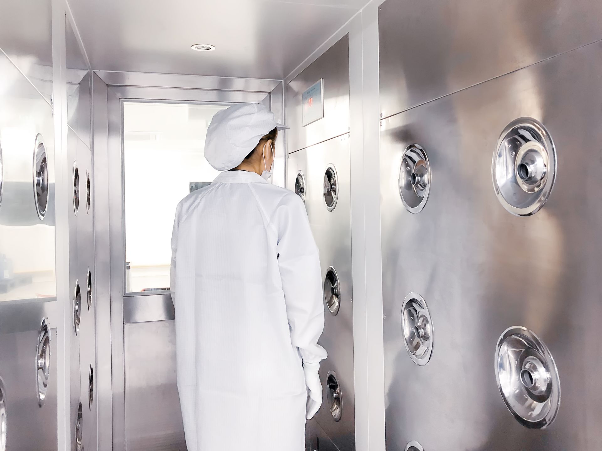

1. Airflow Design


The flow of air within a cleanroom is essential for maintaining cleanliness. There are two main types of airflow designs used in cleanrooms:


  • Laminar Flow: Air flows in a single, constant direction, typically from ceiling to floor. This minimizes turbulence and helps to sweep contaminants away from critical areas.
  • Turbulent Flow: Air moves in multiple directions. This is often used in less stringent cleanroom environments where laminar flow is not critical.


Proper airflow helps to ensure that contaminants are consistently removed from the environment and that the room remains within the designated ISO classification.


2. Filtration Systems

High-efficiency particulate air (HEPA) or ultra-low penetration air (ULPA) filters are used in cleanrooms to remove particles from the air. The efficiency of these filters is key to achieving and maintaining the required cleanroom class. Regular maintenance and replacement of filters are essential for maintaining cleanroom integrity.


3. Room Design and Materials


The design of a cleanroom plays a significant role in its performance. Smooth, non-porous surfaces help to prevent the accumulation of particles. Walls, floors, and ceilings must be easy to clean and resistant to contamination buildup. The materials used for construction should also help maintain the airflow patterns necessary for the cleanroom’s operation.


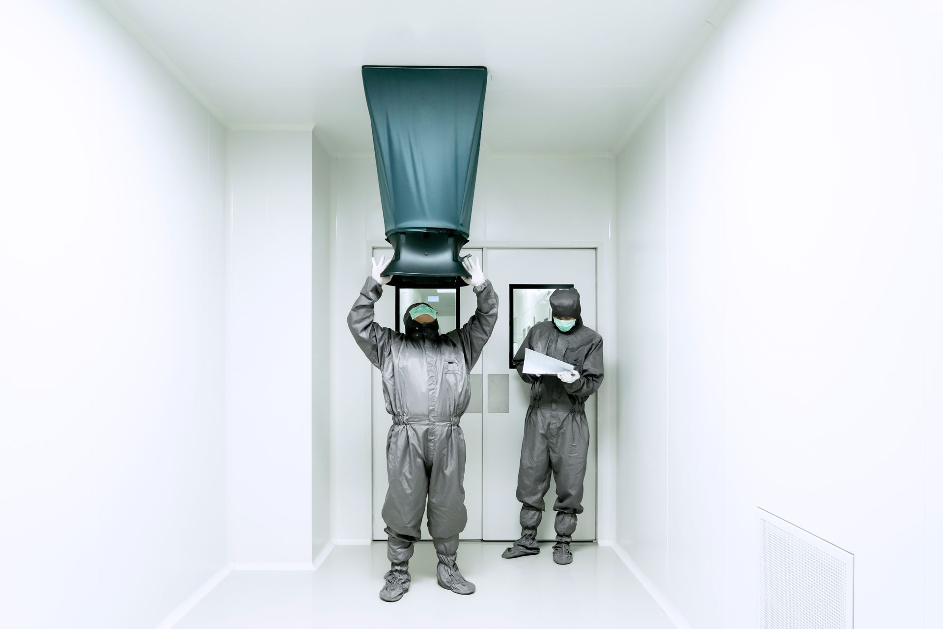
4. Personnel and Gowning Procedures


Personnel working in a cleanroom can be a source of contamination if proper gowning and hygiene procedures are not followed. Cleanroom clothing (e.g., gowns, gloves, masks) prevents particles from shedding from workers’ bodies. The level of personal contamination control required increases with the cleanliness classification of the room.


Application of ISO Classifications Across Industries


ISO classifications are applied in various industries to maintain product quality and ensure the safety of products and processes. The specific class required depends on the level of contamination control needed in each industry.


1. Semiconductor Manufacturing


Semiconductor fabrication is one of the most demanding applications for cleanroom environments. Even microscopic particles can damage delicate microelectronic components. ISO Class 1 to Class 5 cleanrooms are typically required, with stringent controls over particulate matter to maintain the performance and reliability of semiconductor devices.


2. Pharmaceutical and Biotechnology


In the pharmaceutical industry, especially in the production of sterile products like injectables, ISO Class 5 to Class 7 cleanrooms are necessary to prevent microbial contamination and maintain product sterility. The need for sterility in cleanrooms is essential to ensure that drugs and biologics are free from pathogens or contaminants that could jeopardize patient safety.


3. Aerospace


Aerospace manufacturing, especially the production of components for spacecraft and satellites, requires cleanrooms with ISO Class 5 to Class 7 classifications to prevent contamination that could impact the function of sensitive instruments or components in space missions.


4. Medical Devices


The production of medical devices, particularly implants and surgical instruments, requires high cleanliness standards. Cleanrooms with ISO Class 7 or Class 8 are typically used in the assembly and packaging stages to maintain the safety and sterility of medical products.


5. Food Production


In food processing and packaging, cleanrooms with ISO Class 8 or Class 9 are typically sufficient to meet the regulatory standards for hygiene and product safety. However, cleanrooms in the pharmaceutical and biotechnology industries may require higher ISO classifications due to the more stringent requirements for sterility.


Conclusion


ISO classifications are critical in ensuring that cleanroom environments maintain the required levels of cleanliness and contamination control. They provide a standardized framework that helps manufacturers, researchers, and other professionals assess and maintain the cleanliness of their controlled environments. By understanding ISO classifications and their impact on cleanroom operations, industries can implement the necessary systems and processes to meet stringent quality standards, reduce contamination risks, and ensure product safety and reliability.


As industries continue to evolve, so too will cleanroom standards, with ISO classifications playing a fundamental role in maintaining the integrity of the manufacturing and research processes. By adhering to ISO standards, businesses can ensure compliance, improve operational efficiency, and maintain high-quality products in some of the most sensitive and critical industries.


Read more: All About Cleanrooms - The ultimate Guide


Robotic arms assembling circuit boards on a factory production line.
By Kjeld Lund April 1, 2026 April 1, 2026
Smoke Visualization Studies: Interpreting Airflow Behaviour in Critical Zones 1. Introduction Smoke visualization—often referred to as airflow visualization or “smoke studies”—is a core diagnostic tool for assessing airflow behaviour in cleanrooms, particularly within critical Grade A/B aseptic processing zones . EU GMP Annex 1 explicitly requires airflow visualization both at rest and in operation to demonstrate that unidirectional flow adequately protects critical operations, equipment, and product-contact surfaces. This article provides a technically grounded, engineering-focused guide to designing, executing, and interpreting smoke studies to ensure airflow patterns support contamination control and meet regulatory expectations. 2. Purpose and Regulatory Expectations Smoke visualization aims to confirm that airflow behaves as intended, ensuring protection of critical environments by identifying disturbances, dead zones, or reverse flow patterns. Annex 1 requirements include: Demonstrating unidirectional airflow in critical zones with no entrainment of contamination. Showing that interventions, equipment placement, and operator activities do not compromise flow. Recording and documenting both normal operations and “worst-case” conditions. Using visualization outcomes to justify environmental monitoring (EM) locations and risk assessments. Regulators increasingly expect high-quality, well-lit, high-frame-rate video evidence supported by engineering analysis. 3. Principles of Smoke Visualization Smoke studies rely on neutrally-buoyant or near-neutrally-buoyant aerosol streams to reveal airflow direction, turbulence, and obstruction effects. Key principles: Laminarity assessment: Evaluating whether airflow remains uniform and downward across critical surfaces. Turbulence identification: Detecting vortices, backflow, eddies, and stagnation zones. Flow continuity: Ensuring that HEPA-supplied air reaches and sweeps over all areas requiring protection. Disturbance analysis: Assessing how operator movements or equipment operations interrupt airflow. Smoke should follow airflow faithfully without excessive momentum, allowing true visualization of local flow patterns. 4. Smoke Generation and Equipment Selection Selecting appropriate smoke sources is critical to obtaining reliable, interpretable results. Preferred smoke generation systems: Glycol- or glycerin-based theatrical foggers: Provide consistent particle size and visibility. Aqueous-based foggers: Useful where low residue is essential. COâ‚‚-powered smoke sticks or pens: Suitable for small, localized studies but less uniform for large areas. Selection criteria include: Particle size distribution that mimics local airflow without premature settling. Sufficient output to visualize flow while avoiding room overloading. Non-toxic, non-reactive, low-residue formulations compatible with critical areas. Systems must be validated to avoid false interpretation caused by heavy, buoyant, or heat-driven smoke sources. 5. Study Design and Protocol Development A robust smoke study begins with a well-defined protocol linked to the URS, CCS, and DQ rationale . Protocol elements should include: Objectives and acceptance criteria: Clear definitions of expected airflow behaviour. Locations and scenarios: Critical zones (e.g., filling needles, stopper bowls, conveyors). Operator interventions (e.g., aseptic connections, glove port movements). Start-up, steady-state, and operational disturbances. Equipment and material layout: Configured to reflect real or worst-case operating conditions. Airflow setpoints and system parameters: Confirmed and documented before testing. Camera setup: High-resolution, appropriate lighting, multiple angles. Worst-case planning must consider maximum equipment load, maximum personnel presence, and intervention frequency. 6. Executing Smoke Visualization in Unidirectional Flow Zones Critical Grade A areas require consistent downward unidirectional airflow. Smoke studies should show: Smooth, vertical flow lines from HEPA/ULPA filters to the work surface. Minimal turbulence around critical operations such as open product containers. Absence of upward or lateral entrainment that could draw contamination toward sterile items. No stagnation zones behind equipment or within recesses where particles may accumulate. Effective sweeping across entire working surfaces with smoke exiting through low-level returns. Any deviations must be analysed and either justified or rectified through engineering changes. 7. Evaluating Airflow in Barrier Systems (RABS and Isolators) RABS and isolators rely on highly controlled local airflow. Smoke studies must confirm: Integrity of airflow curtains around glove ports and open interventions. Clear separation between operator activities and product flow paths. Protection of transfer zones , particularly during rapid hatch cycling. Absence of backflow when gloves move or during equipment actuation. Isolators may require visualization under both positive and negative pressure, depending on application. 8. Assessing Turbulent-Mixed Airflow Areas In ISO 7–8 backgrounds, smoke visualization is used to: Identify recirculation zones generated by equipment, columns, or heat loads. Confirm airflow direction toward returns and absence of zones where particles may accumulate. Evaluate interactions with operators , especially in high-traffic spaces. Validate airflow behaviour at material transfer points, door operations, and airlocks. This analysis supports risk assessments and informs EM location justification. 9. Interpreting Disturbances and Flow Anomalies Interpretation requires technical competence and a structured approach. Common anomalies include: Eddies behind equipment: Indicate need for repositioning or airflow balancing. Upward thermal plumes above heat sources or operator positions. Cross-drafts from cooling units, door leakage, or improper FFU balancing. Flow “shadowing” caused by improperly placed equipment or tall containers. Jetting from supply diffusers in turbulent areas, creating turbulence at working height. Each anomaly must be assessed for contamination risk and documented with potential mitigations. 10. Linking Smoke Study Results to Risk Assessment Smoke findings must directly support the facility’s Contamination Control Strategy (CCS) and risk assessments. Practical integration includes: Determining environmental monitoring locations based on turbulence zones. Justifying operator positions and movements during aseptic operations. Supporting airflow-related deviation assessments , such as pressure excursions or EM trends. Informing equipment placement , shield design, and layout modifications. Validating worst-case media-fill design , including intervention scenarios. Regulatory reviewers expect clear traceability from smoke visualization to risk controls. 11. Documentation, Video Quality, and Reporting High-quality documentation is essential for regulatory acceptance. Best practices: Use high-resolution video with stable lighting and minimal glare. Capture each scenario from multiple angles , including close-ups of critical points. Provide annotated stills showing key flow behaviours. Document test conditions (supply velocities, pressure readings, equipment states). Provide clear interpretation statements , not merely raw footage. Include a conclusion section summarizing compliance with acceptance criteria. Reports should be retained as controlled documents supporting DQ, OQ, and PQ conclusions. 12. Remediation and Engineering Improvements When smoke studies identify risks, corrective actions may include: Adjusting HEPA airflow balance or diffuser layouts. Reconfiguring equipment or reducing obstruction height. Adding local airflow screens or baffles. Improving operator training and defining motion limits. Modifying process sequences to minimize turbulence during critical exposures. Enhancing airlock performance or reducing door cycling frequency. Changes should be re-tested to confirm effectiveness. 13. Frequency of Smoke Studies and Lifecycle Application Annex 1 requires smoke visualization not only for initial qualification but also during lifecycle operation. Recommended frequency: Initial OQ and PQ for all critical areas. After major layout or equipment changes that affect airflow. Periodically (e.g., every 1–3 years) based on risk. As part of investigations into contamination events or EM excursion trends. Results help ensure the cleanroom’s airflow remains compliant as processes and equipment evolve. 14. Conclusion Smoke visualization studies provide essential insights into airflow behaviour in critical cleanroom zones. When executed with technical rigor and interpreted through an engineering and contamination-control lens, they reveal subtle but impactful airflow disturbances that may compromise aseptic integrity or product safety. By integrating smoke visualization throughout the qualification lifecycle and aligning results with CCS and risk assessments, facilities can verify that airflow patterns consistently support sterile operations and maintain compliance with ISO 14644 and EU GMP Annex 1 expectations. Read more here: About Cleanrooms: The ultimate Guide
Person in a clean suit working in a high-tech laboratory with complex machinery and computer displays.
By Kjeld Lund March 27, 2026 March 27, 2026
Design Considerations for High-Containment Cleanrooms (BSL-3/BSL-4) 1. Introduction High-containment cleanrooms operating at BSL-3 and BSL-4 sit at the intersection of cleanroom engineering, biosafety, and high-reliability facility design. Unlike conventional ISO-classified cleanrooms that primarily protect product, BSL-3/4 facilities must simultaneously protect personnel, environment, and product from highly infectious (and in some cases life-threatening) biological agents. This article outlines key engineering and architectural design considerations for high-containment cleanrooms, focusing on airflow, pressure regimes, containment barriers, decontamination systems, and integration with ISO 14644-style cleanroom performance where product protection is also required (e.g., vaccine or biologics manufacturing). 2. Dual Objectives: Containment and Cleanliness BSL-3 and BSL-4 facilities often function as containment cleanrooms , where the primary objective is to prevent escape of hazardous agents , while in some applications also maintaining defined ISO cleanliness levels for process quality. Core design objectives include: Containment: Maintain negative pressure relative to surrounding areas; ensure all air is appropriately filtered and/or treated. Product protection: Where needed, achieve ISO-classified environments for aseptic processing or contamination-sensitive work. Personnel protection: Provide safe, ergonomic working conditions with well-defined PPE strategies. Environmental protection: Ensure no unfiltered or untreated discharge of hazardous agents to the external environment. Design must reconcile sometimes competing needs (e.g., negative pressure for containment vs. unidirectional flow for product protection) using zoning, isolators, or secondary containment concepts. 3. Zoning, Layout, and Functional Flows Effective zoning is fundamental to high-containment design. Key layout principles: Clear containment boundary: A well-defined perimeter separates containment from non-containment areas, typically with pressure gradients more negative towards the highest-risk rooms . Personnel flow: Linear, with staged entry and exit sequences (change rooms, PPE donning/doffing, showers where required at BSL-4). Material flow: Segregated entry and exit paths with dedicated airlocks, pass-through autoclaves, or chemical dunk tanks/kill tanks as appropriate. Segregation of clean and dirty workflows: Avoid crossing paths between incoming sterile items and outgoing contaminated waste. Support spaces: Equipment rooms, mechanical spaces, and decontamination areas located to allow service access from the non-containment side wherever possible. Workflow and zoning must be documented in the facility’s biosafety risk assessment and contamination control strategy. 4. Pressure Regimes and Airflow Concepts Unlike standard cleanrooms that operate under positive pressure, BSL-3 and BSL-4 suites are designed as negative-pressure facilities . Design considerations: Pressure cascade: Surrounding areas (e.g., corridors) at higher pressure than containment rooms. Most negative pressures usually in rooms with highest risk procedures (e.g., aerosol generation, animal work). Typical room-to-room differentials in the range of –10 to –30 Pa , with overall suite negative pressure relative to building. Airflow direction: Always from low-risk to high-risk areas, and from clean support zones towards laboratories and animal rooms. Exhaust dominance: Exhaust airflow intentionally exceeds supply to maintain negative pressure; leakage paths (doors, penetrations) are controlled and validated. Air change rates (ACH): Frequently higher than in conventional labs; design often targets ≥12 ACH for BSL-3 and higher for certain BSL-4 or animal rooms, adjusted based on heat loads and risk. Where both containment and product cleanliness are needed, localized unidirectional airflow devices, biosafety cabinets (BSCs), or isolators are used to provide ISO-class environments within a negative-pressure room. 5. Filtration and Air Treatment Filtration is central to preventing environmental release of hazardous agents. Key elements: HEPA filtration of exhaust: All exhaust air from BSL-3 and BSL-4 areas passes through at least one stage of HEPA filters , with many BSL-4 designs using two HEPA stages in series housed in validated, testable housings. Supply air treatment: Typically HEPA-filtered when product or surface cleanliness is required. For containment-only spaces, supply may be prefiltered and temperature/humidity-controlled but not always HEPA-filtered unless risk assessment requires it. Filter housings: Must be designed for safe filter change (bag-in/bag-out systems) to avoid operator exposure. Must provide ports for in-situ HEPA integrity testing (e.g., PAO/DEHS challenge). Redundancy: Critical exhaust fans commonly configured in N+1 redundancy with automatic switchover. Failure scenarios must be addressed through emergency power, dampers, and safe-shutdown procedures. Filter system design must be tightly integrated with airflow balance and pressure control strategies. 6. Building Envelope Integrity and Containment Barriers High-containment cleanrooms require a gas-tight or near gas-tight envelope to ensure containment. Architectural considerations: Sealed construction: Continuous, sealed wall and ceiling systems; penetrations (pipes, conduits, ducts) carefully sealed with compatible materials. Monolithic or tightly joined floor systems with continuous coved skirting. Door systems: Airtight doors with robust gasketing and threshold seals. Interlocks for airlocks (personnel and material), preventing simultaneous opening of opposing doors. Leak testing: Room integrity verified via pressure decay or tracer gas tests as appropriate. Envelope performance should be re-verified periodically and after significant modifications. Windows and glazing: Limited and appropriately sealed; often double-glazed with integral blinds on the safe side. Envelope quality directly impacts required exhaust volumes, system energy consumption, and the reliability of pressure cascades. 7. Decontamination Systems and Waste Handling Facilities handling high-risk biological agents must safely inactivate contaminants before discharge. Typical systems: Effluent decontamination: Thermal (heat-based) effluent decontamination systems (EDS) for liquid waste streams. Chemical treatment systems where applicable, with validated contact times and mixing. Solid waste: Pass-through autoclaves at the containment boundary. Dedicated waste handling routes, with appropriate bagging and secondary containment. Room or area decontamination: Fixed or mobile vaporized hydrogen peroxide (VHP) or other gaseous decontamination systems for rooms, isolators, and BSCs. Design must include compatible materials, sealing provisions, and venting strategies. Spill management: Built-in floor drainage strategies (where used) must include traps and decontamination capabilities. SOPs and materials for rapid spill response must be compatible with finishes and effluent systems. Decontamination systems must be validated, and their capability documented within the biosafety management system. 8. Integration of Cleanroom and Biosafety Standards While ISO 14644 provides a framework for air cleanliness, biosafety standards and guidelines (e.g., WHO, CDC/NIH BMBL, national biosafety regulations) define containment expectations. Integration strategies: Define which rooms or work zones require specific ISO classes (e.g., ISO 7 background with ISO 5 BSC or isolator) while maintaining negative pressure relative to adjacent spaces. Use primary containment devices (Class II/III BSCs, isolators) to provide product protection and personnel protection within a BSL-3 or BSL-4 envelope. Align qualification and monitoring routines with both sets of expectations, e.g.: ISO 14644-based particle counts for cleanroom performance. Biosafety commissioning and certification (e.g., BSC testing, containment verification, HEPA integrity tests, pressure testing). Design documentation should show explicit cross-links between ISO-based cleanroom performance criteria and biosafety requirements. 9. Control and Monitoring Systems High-containment facilities require robust monitoring and control to maintain safe operation. Key elements: Continuous pressure monitoring between rooms and relative to non-containment areas, with trend logging and alarm functions. Airflow status and fan monitoring , including exhaust fan interlocks and automatic dampers to maintain safe conditions during failures. Integration with Building Management System (BMS) and Environmental Monitoring Systems (EMS): Alarm prioritization for loss of negative pressure, fan failure, HEPA filter differential pressure excursions, and door interlock failures. Emergency modes: Defined sequences for power loss, fire, and evacuation. Fail-safe damper positions and default airflow paths to prioritize containment. Control strategies must be validated during commissioning and OQ (operational qualification), with clear SOPs for response to alarms and excursions. 10. Personnel and Material Airlocks Airlocks are critical interfaces for maintaining containment while allowing necessary movement. Design features: Personnel airlocks (PALs): Multi-stage change rooms with defined zones for street clothes, facility clothing, and PPE. For BSL-4, often includes mandatory showers on exit , with design to prevent bypass. Material airlocks (MALs): Segregated paths for clean materials in and contaminated materials out. Pass-through autoclaves or chemical decontamination chambers at the containment boundary. Pressure gradients within airlocks: Carefully designed setpoints to ensure flow from “clean” to “dirty” directions, aligned with overall containment cascade. Interlocks and controls: Door interlocking to prevent undesired open-door combinations. Visual indicators of pressure status and door permission states. Airlock design must reflect operational throughput needs without compromising containment. 11. Qualification, Commissioning, and Periodic Re-Verification High-containment cleanrooms require rigorous lifecycle qualification and re-certification. Typical activities: Commissioning: Verification of HVAC, control systems, alarms, autoclaves, and effluent decontamination under static and dynamic conditions. Qualification (DQ–IQ–OQ–PQ): DQ: Demonstrate that design meets biosafety and cleanroom requirements. IQ: Confirm installation of all containment features, filters, and systems as designed. OQ: Verify pressure cascades, airflow patterns, HEPA integrity, envelope leak tightness, decontamination systems, and control logic. PQ: Demonstrate stable performance under real operational conditions, including mock or actual process simulations. Periodic re-verification: Annual or more frequent HEPA integrity testing, pressure verification, BSC certification, and functional checks of decontamination systems. Envelope leak tests and system stress tests at defined intervals. All results must be meticulously documented to support biosafety approvals and regulatory inspections. 12. Conclusion Designing high-containment cleanrooms at BSL-3 and BSL-4 levels demands a sophisticated integration of containment engineering, cleanroom design, and biosafety principles . Robust zoning, negative-pressure cascades, HEPA-filtered exhaust, tight architectural envelopes, validated decontamination systems, and resilient control architectures are core to safe and compliant operation. By addressing these design considerations systematically and aligning them with both ISO 14644 and biosafety guidance, organizations can construct facilities that protect personnel, the environment, and products while enabling advanced research and manufacturing involving high-consequence biological agents. Read more here: About Cleanrooms: The ultimate Guide
Two people in protective suits examine equipment in a cleanroom.
By Kjeld Lund March 20, 2026 March 20, 2026
Particle Deposition Dynamics on Surfaces in ISO-Classified Areas 1. Introduction Particle deposition is a critical contamination mechanism in ISO-classified cleanrooms, particularly where surface cleanliness directly affects product quality, sterility assurance, or device reliability. While ISO 14644-1 and -2 focus primarily on airborne concentration limits, surface contamination plays an equally important role in cleanroom control strategies—especially in aseptic processing, microelectronics, and high-precision manufacturing. Understanding particle deposition dynamics enables engineers and operators to design facilities, workflows, and monitoring programs that minimize risk. This article examines the mechanisms governing deposition, the influence of cleanroom design and operation, and practical strategies for managing surface contamination. 2. Fundamentals of Particle Deposition Particle deposition occurs when airborne particles migrate toward and settle onto surfaces. The deposition rate depends on both particle characteristics and the local airflow environment. Primary physical mechanisms include: Gravitational settling: Dominant for larger particles (≥5–10 µm), dependent on particle density and air viscosity. Turbulent diffusion: Important for smaller particles (<1 µm), where Brownian motion causes random movement toward surfaces. Inertial impaction: Occurs when particles cannot follow rapid changes in airflow direction, particularly near obstructions. Interception: Occurs when particle trajectories skim near surfaces such as HEPA filter housings or equipment edges. Electrostatic effects: Can influence deposition in low-velocity regions or on charged surfaces, though typically secondary in well-grounded facilities. These mechanisms interplay differently depending on cleanroom grade, flow regime, and surface geometry. 3. Influence of ISO Classification and Airflow Regimes ISO class does not directly specify surface cleanliness limits, but it strongly influences deposition rates via air cleanliness and airflow characteristics. ISO 5 (unidirectional flow): High airflow velocities (typically 0.36–0.54 m/s) minimize residence time of particles near surfaces. Deposition is dominated by interception and impaction , particularly around equipment that disturbs downward flow. Well-designed unidirectional zones have low deposition rates on horizontal surfaces. ISO 7–8 (turbulent-mixed): Air changes per hour (ACH) vary from ~20 to >50, depending on process load. Turbulence increases residence time and enhances diffusion-driven deposition , especially for submicron particles. Large obstructions and heat sources produce localized eddies that increase deposition risk. Airflow visualization and CFD modelling help identify areas of stagnation, recirculation, and high deposition potential. 4. Role of Surface Orientation and Geometry Surface orientation has a major effect on deposition dynamics. Horizontal upward-facing surfaces (e.g., worktops, equipment housings): Highest deposition due to gravitational settling. Vertical surfaces: Lower deposition, dominated by diffusion and interception. Recessed or shielded areas: Tend to accumulate particles due to low-velocity “dead zones.” Complex geometries: Sharp edges, corners, and cable bundles enhance turbulent deposition and make cleaning more difficult. Minimizing horizontal and complex surfaces is a cornerstone of hygienic design in EU GMP Annex 1 compliant facilities. 5. Particle Sources and Their Impact on Deposition Particles that deposit on surfaces originate from multiple sources, each with distinct size distributions and behaviors. Common sources include: Personnel: Largest contributor in most cleanrooms; shedding rates increase with movement and improper gowning. Equipment: Motors, bearings, moving parts, and heat-generating components. Processes: Powder handling, machining, filling line operations. Facility envelope: Door leakage, panel edges, worn seals, and construction defects. Cleaning activities: Ironically can elevate deposition if airborne disturbance is excessive or if residues attract particles. Understanding source contributions is essential for designing monitoring programs and establishing cleaning frequencies. 6. Deposition Velocity and Quantification Deposition is often expressed using deposition velocity (vd) , a parameter that relates airborne particle concentration to surface deposition rate. The relationship is typically represented as: Deposition Rate (particles/cm²·h) = Airborne Concentration (particles/m³) × vd Typical deposition velocities: Submicron particles: very low (dominated by diffusion). 1–10 µm particles: moderate; influenced by turbulence and settling. 10 µm particles: high; dominated by gravity. Experimental data and CFD-based estimations can be used to evaluate deposition risk at critical locations. 7. Environmental and Operational Factors Affecting Deposition Deposition rates depend strongly on local environmental conditions. Key influencing factors: HVAC system performance: Variability in air change rates, HEPA supply uniformity, and pressure cascades. Airflow disturbances: Door openings, equipment motion, glovebox operations, and operator movement. Thermal plumes: Heat from equipment or personnel can draw contaminated air upward. Humidity: Affects particle agglomeration; larger agglomerates settle more quickly. Surface electrostatic charge: Can attract fine particles, particularly polymers and textiles. Operational discipline is therefore essential to keeping deposition rates within acceptable limits. 8. Deposition in Aseptic and Critical Grade A/B Areas In Grade A unidirectional airflows, surface deposition directly threatens aseptic integrity. Key considerations: Even minor disruptions (e.g., rapid operator hand movements) can generate turbulence and increase deposition. Equipment layout should minimize obstructions and preserve unidirectional flow paths. Interventions must be minimized; robotic systems or RABS/isolators significantly reduce deposition risk. Frequent cleaning of exposed horizontal surfaces is required, validated for removal of particles and residues. In Grade B support zones, deposition influences airborne contamination levels and therefore overall aseptic performance. 9. Monitoring and Assessing Surface Deposition ISO 14644-9 and -17 provide structured approaches for assessing surface cleanliness and deposition. Practical monitoring tools include: Surface particle counters (for sensitive manufacturing, e.g., microelectronics). Tape-lift or gel tape methods for capturing deposited particles. Microscopy-based analysis (optical or SEM) for size distribution studies. Settle plates for viable particle deposition, used primarily in GMP environments. Data from surface monitoring complement airborne data and support risk evaluations for cleaning frequency and intervention design. 10. Minimizing Deposition Through Design Engineering design plays a critical role in controlling deposition. Effective design measures include: Optimized HEPA placement to maintain uniform flow and minimize recirculation. Reducing obstructions in laminar flow zones; placing equipment out of the airflow path where feasible. Hygienic design of furniture and equipment , minimizing ledges and horizontal surfaces. Sealed cable management to avoid dust-accumulating recesses. Material choices that resist electrostatic charging. These strategies should be evaluated during Design Qualification (DQ) and supported by CFD analysis where appropriate. 11. Operational Controls to Limit Deposition Operational behavior significantly impacts deposition rates. Key practices include: Controlled movement patterns for personnel to avoid disturbing airflow. Minimized interventions and use of automated systems where feasible. Validated cleaning frequencies based on deposition risk and monitoring results. Gowning discipline , including correct fit and material selection. Door management , using airlocks and interlocks to maintain pressure stability. These controls form part of the facility’s contamination control strategy (CCS). 12. Implications for Cleaning and Disinfection Programs Understanding deposition informs cleaning strategies and SOP design. Important considerations: Frequency: High-risk areas require more frequent cleaning due to greater deposition load. Technique: Wiping patterns and overlap must remove not only microbial but also particulate contamination. Tool selection: Low-lint materials and validated pre-saturated wipes reduce particle re-distribution. Residue management: Some cleaning agents increase tackiness or static, inadvertently increasing deposition—requiring validation and rotation strategies. Cleaning validation should demonstrate removal efficiency for relevant particle sizes. 13. Integrating Deposition Data Into CCS and Lifecycle Management Deposition knowledge supports long-term contamination control planning. Lifecycle measures include: Trending surface contamination levels alongside airborne data. Evaluating deposition patterns after layout changes or new equipment installation. Trigger-based cleaning enhancements following deviations or adverse trends. Design updates when chronic deposition hot spots persist. Reassessment during requalification to verify that deposition behavior remains consistent. This integrated approach aligns with the continuous improvement expectations of EU GMP Annex 1 and ISO 14644-2. 14. Conclusion Particle deposition on surfaces in ISO-classified cleanrooms is a multidimensional phenomenon shaped by airflow behavior, particle physics, facility design, and operational practice. By understanding deposition dynamics and integrating this knowledge into monitoring, cleaning, and CCS strategies, facilities can significantly reduce contamination risk, support regulatory compliance, and enhance long-term cleanroom performance. A disciplined, engineering-driven approach ensures that surface cleanliness is not an afterthought but a controlled and verifiable element of the cleanroom environment. Read more here: About Cleanrooms: The ultimate Guide
Show More